
Machine and vehicle manufacturers grow by entering new applications, offering more configurations, and responding to increasingly specific customer requirements.
Growth takes many forms: a new model size, attachment, hydraulic configuration, operator interface, body layout, safety function, power requirement, or customer-specific option package. Each variation may open a valuable commercial opportunity—but only if the underlying electronic architecture can support it without multiplying cost and complexity.
When every configuration introduces unique controllers, harnesses, software, test plans, work instructions, replacement parts, and diagnostic procedures, product growth does more than raise costs. It can cause engineering, manufacturing, inventory, quality, and field-support costs to grow disproportionately—potentially outpacing the incremental revenue or customer value the new variant is intended to create.
A scalable control platform changes the equation. Instead of treating every model as a separate controls project, the OEM establishes a common foundation that can be reused and configured across the product family.
The objective is not to eliminate variation. It is to move variation to the layers where it can be managed most effectively.
Product variation creates costs beyond the bill of materials
The cost of a new configuration is often evaluated through component pricing and initial engineering hours. That view is incomplete.
A configuration-specific architecture can create additional work throughout the product lifecycle:
- Engineering maintains unique schematics, I/O assignments, control logic, display applications, and network configurations.
- Manufacturing manages additional harnesses, routing instructions, connectors, test procedures, and assembly exceptions.
- Supply chain teams forecast and purchase more part numbers, often at lower individual volumes.
- Quality teams determine which hardware and software combinations apply to each build.
- Service teams identify the correct replacement components and diagnostic procedures for each configuration.
- Product teams must fit future functions into architectures that may already be approaching their I/O, memory, communication, or packaging limits.
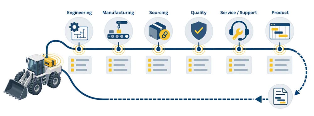
This is why a seemingly small customer option can create a much larger operational footprint. The option itself may require only one sensor, switch, valve, or output. Supporting it may also require changes to the harness, logic, documentation, test coverage, inventory structure, service information, and technician training.
Therefore, the right metric is not simply the material cost of the option, it is the total amount of lifecycle investment needed to support it.
Separate what is common from what is configurable
A scalable controls strategy begins by defining which parts of the machine architecture should remain common across the product family.
Depending on the equipment, that reusable foundation may include:
- CAN or CAN-FD network structure
- Communication protocols and message conventions
- Controller family and programming environment
- Power distribution strategy
- Distributed I/O architecture
- Operator-interface conventions
- Diagnostic and fault-handling logic
- Reusable software functions
- Harness connection and pinout strategies
- Validation methods
- Service tools and replacement practices
Application-specific behavior can then be managed through controller sizing, configurable I/O, software parameters, display configuration, keypad graphics, feature enablement, or additional distributed modules near the affected machine functions.
This preserves the ability to build different machines without allowing each one to become a separate electronic ecosystem.
Standardization does not mean every machine receives identical hardware or behavior. It means related machines use a controlled set of building blocks, interfaces, engineering methods, and diagnostic conventions.
Hardware commonality must support more than one machine size
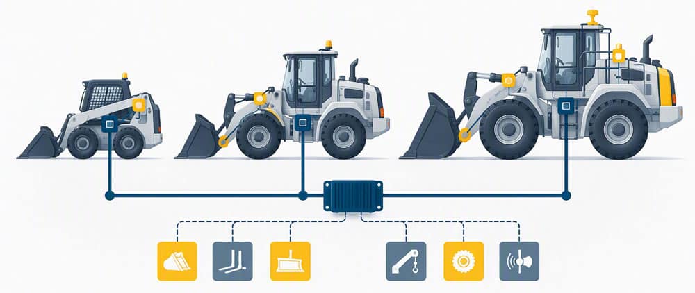
A platform cannot scale effectively if moving to a larger or smaller machine requires replacing the entire development environment. Controller families based on a common architecture give engineers a more practical way to match I/O capacity to each application while preserving software, communication, and electrical design work.
For example, HED’s CL-4000 Series controllers share a common architecture designed to support software reuse between controller models. Common wire pinouts also provide a clearer expansion path when a future machine or configuration requires additional I/O.
The CL-4004 extends this approach for applications with higher I/O and processing requirements. Software-configurable I/O helps teams adapt the controller to application needs without creating unnecessary hardware variations.
A coordinated controller family provides two important types of scalability:
- Scalability across machine programs: Engineering teams can carry proven software structures, communication methods, and design patterns into the next model.
- Scalability within a program: The OEM can select appropriate I/O and communication capacity for a configuration without moving to an unrelated architecture.
The objective is not simply to have multiple controller sizes available. It is to create a product family in which design knowledge moves with the application.
Keep machine options from expanding the entire harness
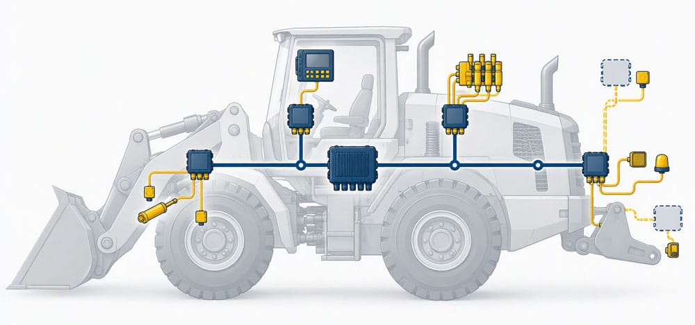
Machine options become particularly expensive when every possible feature must be wired back to a central enclosure. This can lead to oversized harnesses containing circuits that are not used on every build. It may also add wire length, routing congestion, connectors, holes, keep-out areas, assembly handling, and potential fault points.
A CAN-based backbone with distributed I/O provides another approach. I/O can be placed closer to the controlled functions, allowing the OEM to add capacity where the option is physically installed. Software-defined behavior can adapt the function without redesigning the entire electrical system.
The potential benefits include:
- Shorter wire runs
- Less routing congestion
- Smaller centralized harnesses
- More usable packaging space
- Fewer unused circuits
- Easier option installation
- More consistent communication between machine functions
- Better fault isolation
This approach is especially relevant to vocational vehicles, emergency apparatus, utility equipment, lifting platforms, construction machines, and other products in which customer-specific layouts or option packages are part of the business model.
The business advantage is not simply less wiring. It is the ability to support configuration choices without allowing those choices to multiply through the entire electrical design.
Software reuse must be designed
Common hardware does not automatically create a common platform. Software can still fragment if every project creates separate signal definitions, diagnostic behavior, feature logic, display conventions, or communication structures.
A reusable software strategy should define:
- Which machine functions are shared across the product family
- Which behaviors are controlled through parameters
- Which features can be enabled or disabled through configuration
- Which interfaces remain stable when hardware capacity changes
- Which functions require application-specific validation
- How software versions and configurations are identified
- How diagnostics remain consistent across variants
The distinction is important. Copying a previous program and modifying it creates another software branch. Developing reusable functions and controlled configuration rules creates a platform asset.
A common controls foundation can still support application-specific behavior at the software and I/O levels. An excavator, utility truck, lifting platform, and emergency vehicle do not need identical functionality. However, an OEM’s related models can use consistent communication, diagnostic, software, and hardware strategies.
Discuss Your Platform Architecture with HED
Validation reuse requires configuration control
A scalable platform can reduce repeated validation, but only when the engineering team clearly understands what has remained unchanged and what has not.
Reusing a controller or software library does not mean a new vehicle configuration is automatically validated. Each machine or vehicle still requires application-level analysis and testing based on its performance, operating environment, safety requirements, and intended use.
The opportunity is to structure validation so the team does not repeatedly prove unchanged behavior. A practical platform-validation model separates the system into three categories.
1. Common platform elements
These are interfaces, communication methods, hardware behaviors, and software functions intended to remain unchanged across the product family. Validation evidence should be documented and controlled for appropriate reuse.
2. Configurable elements
These include parameters, I/O assignments, feature settings, display pages, and option combinations that can change within defined boundaries. Validation should confirm that permitted configurations operate correctly. It should also address invalid or conflicting selections.
3. Application-specific elements
These include machine dynamics, hydraulic behavior, safety-related functions, unique attachments, customer-installed equipment, and other interactions that depend on the final machine. These elements require application-specific analysis and testing.
This structure does not eliminate validation. It makes the source of change visible so validation effort can follow actual technical risk rather than treating every variation as a completely unrelated system.
Include the operator interface in the platform strategy
Controls standardization is weakened when the operator interface is redesigned independently for every model.
Displays and keypads can support platform reuse by maintaining common symbols, control locations, machine-state conventions, fault presentation, and diagnostic logic while allowing graphics and behavior to be configured for the application.
Configurable, CAN-connected keypads can provide machine input, status indication, diagnostic feedback, and software-defined control behavior. Across an equipment family, the same keypad strategy can provide consistency while still supporting application-specific functions.
When related machines use different interface layouts, symbols, control sequences, or feedback conventions, operators must relearn how to perform familiar tasks each time they move between models. That adjustment can increase training time, slow productivity, and make it harder for experienced operators to transfer their skills across the OEM’s product family.
A common operator-interface approach may reduce training time, shorten the learning curve when operators move between related machines, and help experienced users become productive more quickly. It may also simplify:
- Operator movement between related machines with less relearning of controls, symbols, and operating conventions
- Assembly and replacement procedures
- Technician familiarity
- Documentation development
- Software maintenance
- Future feature deployment
The platform strategy should include the human-machine interface rather than stopping at the controller. Consistent interaction patterns across related machines can reduce the time spent training operators and help them carry familiar operating methods from one model to the next.
Treat serviceability as an architecture decision
Configuration cost continues after the equipment enters the field. If every variant uses different fault codes, diagnostic tools, connectors, replacement parts, or troubleshooting procedures, the service organization must support each one as a separate system.
Consistent diagnostic logic and fault visibility can help technicians move between related machines without learning a completely different process for every configuration.
Before releasing a platform, determine:
- Whether the same faults have consistent meanings across models
- Whether service data is available through common interfaces
- Whether replacement modules require configuration-specific programming
- Whether technicians can identify the installed configuration
- Whether option-level faults can be isolated without tracing the entire harness
- Whether future modules can be added without replacing the service environment
A platform is not truly reusable if the service team must rediscover it on every machine.
What the platform approach looks like in practice
In one HED vehicle application, the manufacturer transitioned from an oversized centralized harness to a distributed control architecture.
Shorter wire runs and simplified routing reduced assembly complexity and opportunities for wiring-related errors and rework. Features and customer-specific options could be configured within the control system, while the distributed architecture helped technicians isolate functionality during troubleshooting.
The most important outcome was broader than the replacement of individual components. The manufacturer established a configurable electrical platform that could support additional features and future vehicle programs without requiring a complete control-system redesign.
The takeaway applies beyond one vehicle type. When electronics are treated as an integrated platform, they can help improve production, diagnostics, function coordination, third-party integration, and future program development.
How to evaluate whether your current architecture scale?
An OEM does not have to begin with a complete redesign. Start by measuring where variation currently enters the business.
1. Map the product family
List active models, sizes, trims, attachments, option packages, regional variants, and major customer-specific configurations. Identify which configurations share similar functional needs, even if their current hardware or software differs.
2. Build a variation register
For each configuration, document changes to:
- Controllers and I/O modules
- Harnesses and connectors
- Sensors and outputs
- Network messages
- Software builds
- Display and keypad applications
- Operator-interface conventions, including control placement, symbols, navigation patterns, machine-state feedback, and fault presentation
- Test procedures
- Work instructions
- Service documentation
- Replacement parts
This makes it easier to see when one commercial option creates changes across several downstream systems.
3. Identify repeated engineering
Look for control logic, communications, diagnostics, operator indications, schematics, and test procedures that have been recreated for multiple programs. Repeated work may be a candidate for a controlled platform function.
4. Find capacity cliffs
Document where the current architecture is approaching its limits:
- I/O capacity
- CAN channels
- Processing capacity
- Memory
- Connector capacity
- Power distribution capacity
- Display or camera support
- Physical packaging space
An architecture that works only until the next option is added is not truly scalable.
5. Review diagnostic consistency
Compare fault behavior, service tools, access methods, and troubleshooting documentation across related models. Determine whether a technician familiar with one configuration can efficiently diagnose another.
6. Separate actual requirements from inherited differences
Some variations are required by the application. Others exist because separate programs, suppliers, or engineering teams made different decisions over time. Do not standardize away a legitimate machine requirement. Instead, standardize the interface and method used to meet it.
7. Select a pilot platform
Choose one product family in which a platform approach can be tested and measured. The pilot should include enough variation to prove the concept without introducing unnecessary program risk. Use the results to refine the architecture before extending it to other programs.
8. Establish platform metrics
Track measures that show whether the architecture is reducing complexity:
- Percentage of control software reused
- Number of controllers and I/O modules used across the family
- Number of unique harnesses and harness variants
- Number of unique electrical components
- Engineering hours required for a new configuration
- Validation procedures reused versus newly created
- Operator training time for each model and the time required for an experienced operator to reach proficiency when moving between related machines
- Option-related assembly exceptions
- Wiring-related rework
- Diagnostic procedures shared across models
- Service parts unique to one configuration
- Time from configuration approval to production release
These measures turn platform scalability from a design principle into a measurable operating result.
Signs that the control architecture may be limiting growth
An OEM may need to reconsider its control architecture when:
- Adding an option requires a new controller instead of an I/O or software configuration.
- Software cannot move between controller sizes without major redevelopment.
- Closely related models use different harness and diagnostic strategies.
- Existing controllers have little remaining I/O, memory, or communication capacity.
- Technicians need different tools or procedures for similar machines.
- Manufacturing installs unused circuits to support possible future options.
- Operators must relearn control layouts, symbols, or operating sequences when moving between related machines from the same OEM.
- Field replacement requires extensive configuration-specific knowledge.
- New technology cannot be added without redesigning the core electrical system.
- Engineering spends more time maintaining variants than developing new capabilities.
Any one condition may have a reasonable explanation. When several appear together, the cost problem may be architectural rather than component-specific.
What is each new configuration really adding?
Before approving the next machine variant, evaluate its effect on:
- Part numbers
- Harnesses and connectors
- Software branches
- Validation procedures
- Assembly instructions
- Inventory
- Diagnostic logic
- Service documentation
- Replacement parts
- Training requirements
If one option creates changes across all ten areas, the problem may be the architecture rather than the option.
Build the architecture around the next machine
A control system can meet every requirement for the current machine and still constrain the product roadmap. The more useful question is whether the architecture provides a reusable foundation for the next model, attachment, operator-interface requirement, diagnostic capability, or connected feature.
Each machine must still be engineered for its specific application. The competitive advantage comes from deciding which engineering work should not have to be repeated. Every new configuration should add customer value without adding an entirely new control-system lifecycle.
If each product variation is multiplying hardware, harnesses, software branches, test plans, inventory, and service procedures, it may be time to evaluate the platform beneath the products.
Evaluate your control platform with HED
HED works with OEM engineering teams to connect operator interfaces, control logic, I/O, power distribution, communication networks, diagnostics, and machine functions in a coordinated control architecture.
The discussion can begin with an existing machine, a next-generation program, or a specific configuration that has become difficult to build, validate, or support.
Request a system architecture review to identify where your current approach supports reuse, where product variation is creating downstream complexity, and where a scalable control platform could reduce repeated engineering across the product family.